> >
Composte Beam Design
|
|
Download Sample Report |
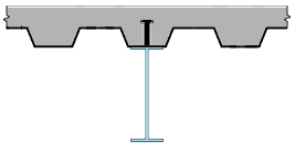
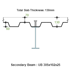
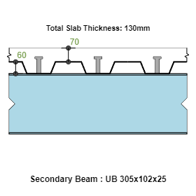
Composite Beam comprises of a standard steel section supporting the metal deck with concrete. After the concrete has hardened, concrete and the steel beam act together to resist the loads by composite action. The shear transfer of concrete compression to the steel section is achieved by welding the studs along the beam span. This composite property is much higher than the steel beam property alone thereby achieving higher load carrying capacity.
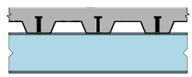
Usually the concrete is cast over the metal deck and the metal deck is attached to the top flange of the steel section along with studs. The metal deck acts as a formwork for concreting and the steel beam is supporting the concrete weight and the construction loads during the construction activity.
Features
- ECCOMPBEAM is used to design the composite beam made of steel section I shape and the concrete for different load cases and combinations at Construction and Final Stages.
- Design Options
- Composite and Non-Composite Design
- Supported (Shored) or unsupported during construction
- Design Standards
- American – LRFD
- American – ASD
- Section
- Standard Table: American, British and European Shapes
- Beam and Span
- Primary Beam
- Secondary Beam
- Edge Located
- Intermediate Located
- User Defined Location
- Deck Directions
- Transverse and Longitudinal to Beam Span
- Lateral Restraints
- Fully Restrained, Partially Restrained and option to select at 1/nth locations
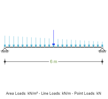
- Loads
- Uniform Area Loads
- Uniform Line Loads
- Point Loads
- Combinations
- Load combinations with deflection ratio for long and short term
Design Considerations
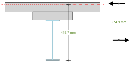
- Option to select Composite or Non-Composite Design Check. When composite option is selcted, the final stage loads are resisted by concrete and steel section composite action.
- Option to consider shoring during construction. This option disables the design check during construction and all the loads at final stage are resisted by composite action.
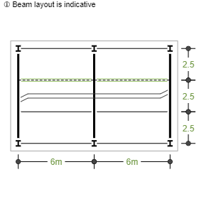
- The beam location can be primary and secondary. For primary beam type, the loads from the secondary beams are calculated by the software. This saves the user having to calculate the secondary beam loads to the primary beam.
- The restraints to calculate the buckling length can be specified. The software automatically calculates the non-uniform moment factor Cb according to AISC 360-05 section (F1-1) and the moments MA, MB, MC and Mmax along the unsupported length to calculate the lateral torsional buckling capacity.
- The option for long term deflection can be specified for the combinations as desired.
References
- ANSI/AISC 360-05 – “Specification for Structural Steel Buildings”
- /ACI 318-19 – “Building Code Requirements for Structural Concrete”
Revision
- Ver 1.1 - Non composite option is enabled
- Ver 1.0 - Initial Version
|
|
Download Sample Report |