Help Topics
ECCOMPBEAM - Composite Beam Design
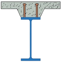
This part of user manual describes how to use ECCOMPBEAM for the design of Composite Beam of a steel section and concrete decking slab. ECPlus applications are designed as wizard type which is a step by step guided input procedure. If you are new to ECPlus applications, click here for general guidance.
Prerequisites: The user is expected to have a basic understanding of structural steel design concepts.
The minimum input data required to use this application is as follows:
- ❶ Structural Steel Section and Grade.
- ❷ Decking details
- ❷ Concrete Properties
- ❸ Loads and Combination.
Design Options
This page allows to select the design standard and unit.
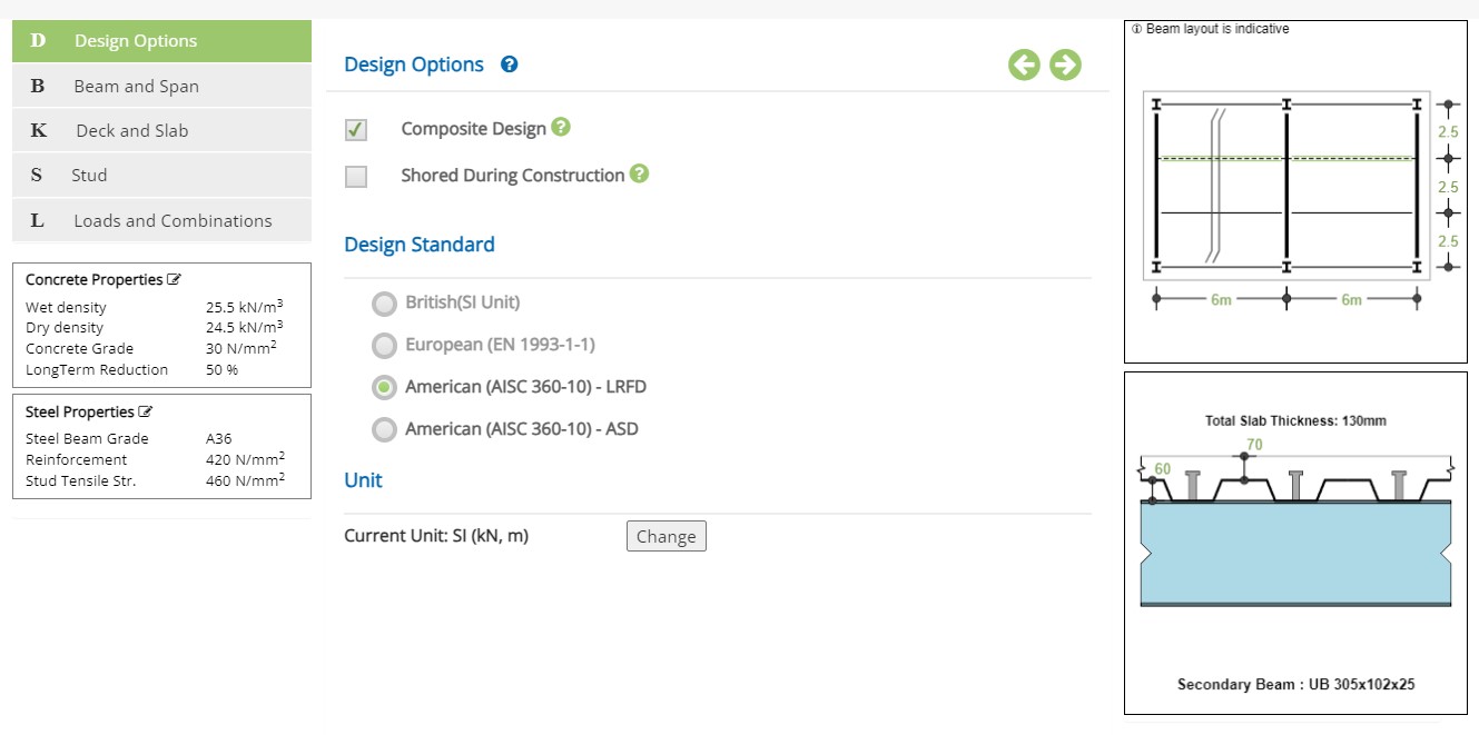
Design Options
☐ Composite Design : Select if composite design is required for the final stage. If not checked, all loads are resisted by the steel beam without composite beam action.
☐ Shoring During Construction : If props are provided to the steel beam and or to the concrete deck during construction, select this option. This will prevent checking the steel beam for construction loads and all final loads are resisted by the composite beam.
Design Standard
Select the National Standard for the design. Available Standards: ☉European, ☉American.
European Standard is not available in the current version.
Unit
It displays the active unit. The unit Change button is displayed when ☉American Standard is selected.
European Standard can not be selected when Imperial unit is active.
Change
Click this button to open the unit change pop-up dialog.
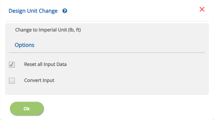
☐ Reset all Input Data
This option will reset the input data for the new unit. This option is recommended if the job is new and no input data has been entered yet.
☐ Convert Input
This option allows to convert previously entered input datas to the new unit.
The user is urged to ensure if conversion is properly applied.
Beam and Span
This page allows to select the span, tyoe of beam and the location within the composite beam layout.
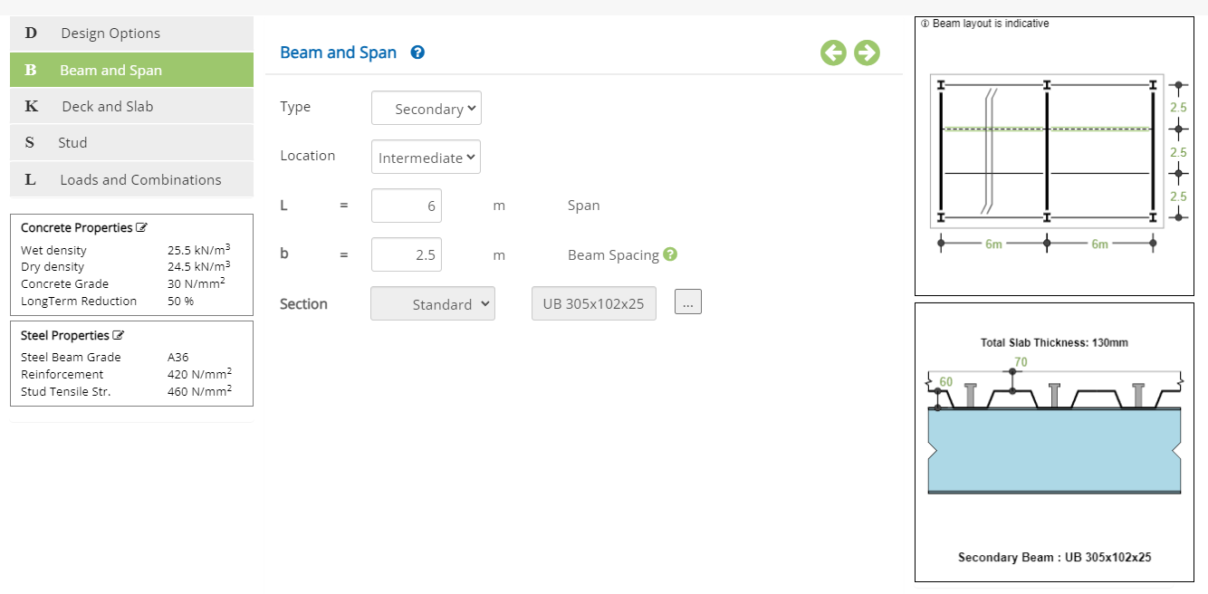 Type
Type▽ Secondary: Select this option if the beam is secondary supported on primary beams.
▽ Primary: Select this option if the beam is primary supporting secondary beams.
When primary beam option is selected, the loads from the secondary beams are auto calculated by the software.
▽ Intermediate: Select this option if the beam is at intermediate location in the beams layout.
▽ Edge: Select this option if the beam is at the edge in the beams layout.
▽ User Defined: Select this option if the user wishes to define the load tributory width and effective width of the concrete slab.
The software calculates the load tributory width and the effective concrete slab width according to the location of the beam.
Enter the span of the beam - L.
↔ Range: 0.09 to 50 m (0.3 to 164.04 ft)
Enter the spacing of the beam in the layout.
↔ Range: 0.09 to 25 m (0.3 to 82.02 ft)
Enter the projection concrete slab from the center of beam
↔ Range: 0.09 to 5 m (0.3 to 16.4 ft)
Enter the effective concrete flange width
↔ Range: 0.09 to 10 m (0.3 to 32.81 ft)
Enter the tributary width from which the distributed loads will be transferred to the beam
↔ Range: 0.09 to 25 m (0.3 to 82.02 ft)
The button ... opens the steel section table pop-up to select the beam steel section as below.
Steel Section Table
This steel section allows the user to select the desired steel section profile.
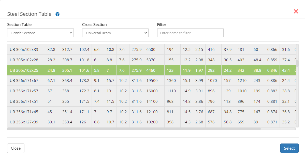 ▽ Section Table:
Select this option to have list of Standard British, European or AISC Sections.
▽ Cross Section:This option allows user to select wider or narrow flange beam like UB, UC, IPE, HE, W, M, etc., based on selection at Section Table menu.
▽ Filter:Based on name by user and with option selected at Section Table and Cross Section , a filtered member list will be displayed.
Secondary Beams
This section appears when the beam type is selected as Primary.
▽ No of Secondary Beams SbnSelect the no of secondary beams supported on the primary beam
Secondary Beam Weight - Sbn↔ Range: 0 to 25 kN/m (0 to 1.71 kips/ft)
Deck and Slab
This page allows to enter the deck details, direction of deck ribs with respect to beam span, slab thickness and restraint conditions .
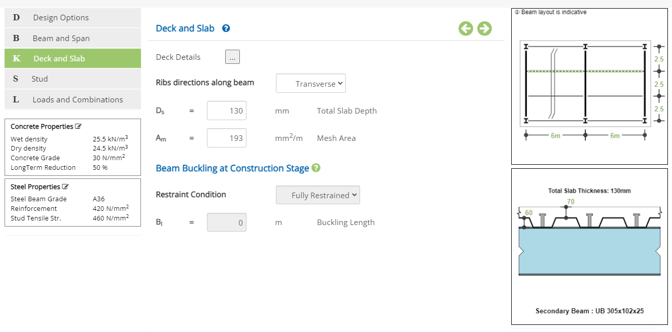 Ribs direction along beam
Select the deck ribs if parellal(longitudinal) and transverse(perpedicular) to beam span.
▽ Transverse: Select this option to deck ribs are transverse(perpedicular) to beam span.
▽ Longitudinal: Select this option to deck ribs are parellal(longitudinal) to beam span.
Enter the total thickness of the concrete slab including the rib part
↔ Range: 50 to 1000 mm (3.54 to 39.37 in)
Enter the reinforcement mesh area
↔ Range: 50 to 1000 mm2/m (0.024 to 0.472 in2/ft)
Information only - not considered in the design.
Beam Buckling at Construction Stage
During construction, the user can define how the beam is restrained against lateral bukcling. This is applicable when the ribs are parellal to the beam span. For transverse ribs, the beam is fully restrained. This is not applicable when the option 'Shored during Construction' is selected.
Restraint Condition▽ Fully Restrained: Select this option if the beam is fully restrained along the beam.
▽ Partially Restrained: Select this option if the beam is partially restrained. The user will then enter the buckling(unrestrained) beam length.
▽ No Restraints: Select this option if the beam has no intermediate restraints.
▽ At Secondary Beams: Select this option if the beam is restrained by the secondary beam locations. (Option is available only for primary beam type)
▽ At Midspan : Select this option if the beam has one restaint at midspan.
▽ At Every 1/n Span : Select this option if the beam is restrained at every 1/nth span.
Enter the bucklilng length of the beam when Partially Restrained option is selected.
↔ Range: 0 to 100 m (0 to 328.08 ft)
Deck Details
The button ... opens the pop-up to enter the metal deck dimensions and weight.
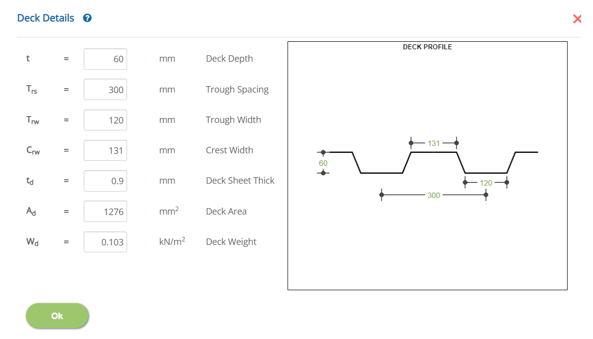 Deck Depth - t
Enter the deck (rib) depth.
↔ Range: 20 to 500 mm (0.79 to 19.69 in)
Enter the spacing of the ribs.
↔ Range: 50 to 2000 mm (1.97 to 78.74 in)
Enter the width of the crest of the rib at top.
↔ Range: 30 to 600 mm (1.81 to 23.62 in)
Enter the thickness of the metal deck sheet thickness.
↔ Range: 0.5 to 5 mm (0.02 to 0.2 in)
Enter the area of the deck panel
↔ Range: 0 to 100000 mm2 (0 to 2402.5 in2)
Enter the deck weight per unit area
↔ Range: 0 to 1.5 kN/m2 (0 to 0.031) ksf
* Marked items are for information only.
Stud
This page allows to enter the stud diameter, height and the spacing along the beam. This option is not applicable when Non-Composite Design option is selected.
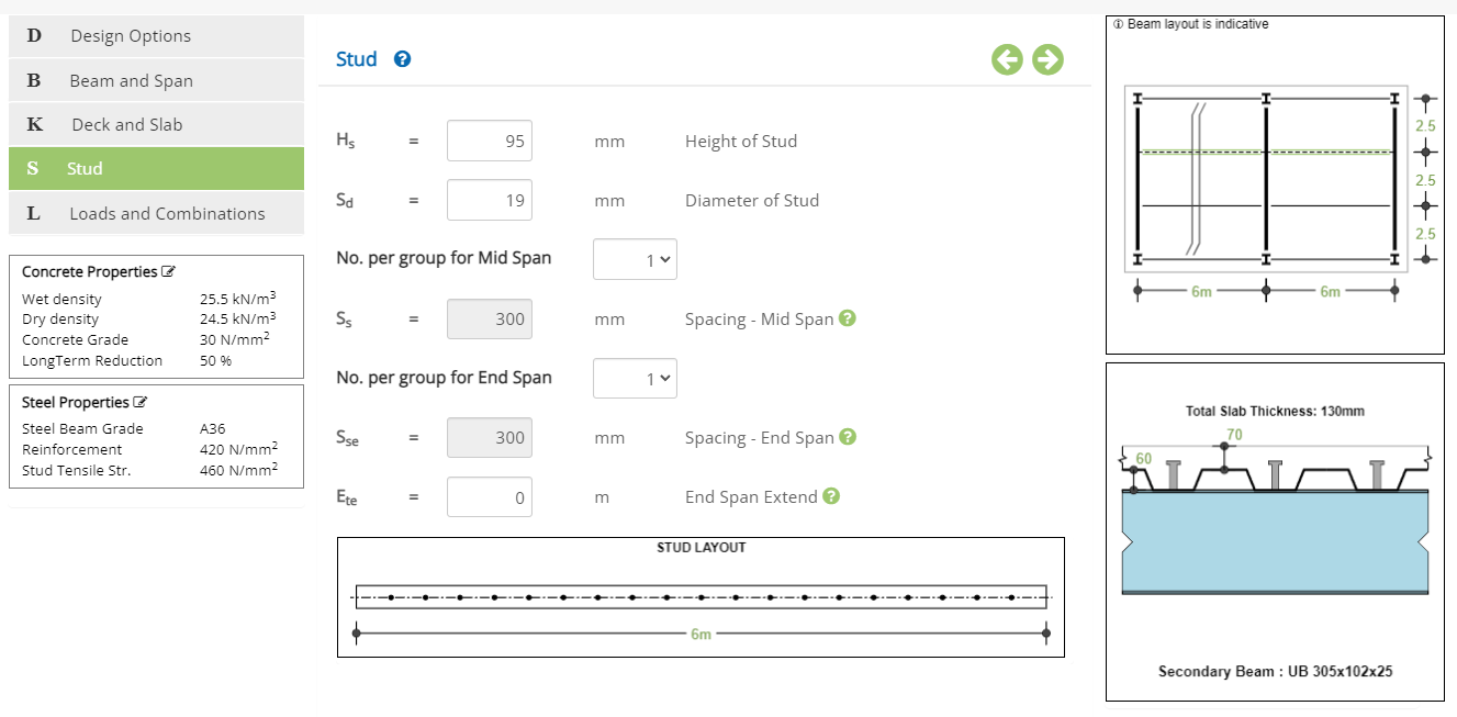 Height of Stud - Hs
Enter the height of the stud including the head from the top of the steel beam flange.
↔ Range: 30 to 1000 mm (1.81 to 39.37 in)
Enter the nominal diameter of the stud.
↔ Range: 10 to 40 mm (0.39 to 1.57 in)
▽ 1: Select this option if the mid span stud is one (1 no) at every spacing.
▽ 2: Select this option if the mid span stud is two (2 nos) at every spacing.
Enter the spacing of the mid span studs.
↔ Range: 50 to 2000 mm (1.97 to 78.74 in)
▽ 1: Select this option if the end span stud is one (1 no) at every spacing.
▽ 2: Select this option if the end span stud is two (2 nos) at every spacing.
Enter the spacing of the end span studs.
↔ Range: 50 to 2000 mm 50 to 2000 mm (1.97 to 78.74 in)
Enter the extend of the end span studs from each support end. Enter zero if there is no different end span stud arrangement.
↔ Range: 0 to 25 m (0 to 82.02 ft)
* Marked item will follow the spacing of metal deck ribs when the ribs are transverse to the beam span.
Loads and Combinations
This page allows to provide the loads and load combination details for the construction and final stages design.
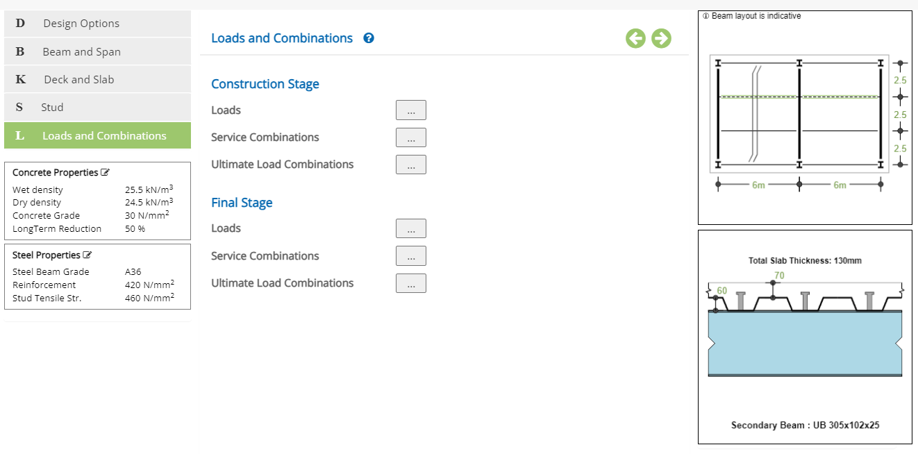
Construction Stage / Final Stage
Loads (Construction and Final Stages)Click button to opens the pop-up dialog to define the load details.
Service Combinations *
Click button to opens the pop-up dialog to define the load combinations at service stage.
Ultimate Combinations * Click button to opens the pop-up dialog to define the load combinations for ultimate design.
* For American ASD combination, only one set of combinations is applicable for service and design check.
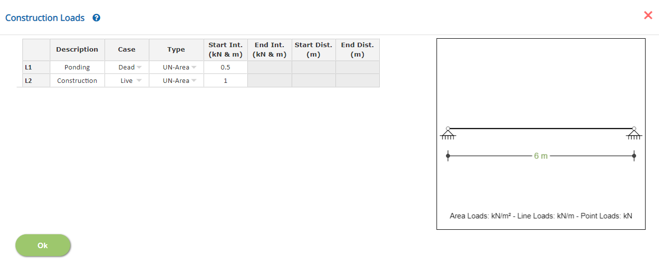
Loads (Construction and Final Stages)
This is a spreadsheet type input dialog - right click to add or delete rows.
DescriptionEnter the description of the load item.
Load Case▽ Load Case: Select the load case from the list of 'Dead', 'Live',...
Type▽ UN-Area: Select this type if the load to be applied is distributed uniform area load. The software calculates the distributed line load from the area load.
▽ UN-Line: Select this type if the load to be applied is distributed uniform line load.
▽ VA-Line: Select this type if the load to be applied is distributed varying line load. The start and end intensity and their locations to be specified.
▽ Point: Select this type if the load to be applied is a point to be appliled at a specific location.
▽ Mid Point: Select this type if the load to be applied is a point to be appliled at mid span.
▽ 2 Points: Select this type if the load to be applied is a point to be appliled at 1/3rd and 2/3rd span.
▽ 3 Points: Select this type if the load to be applied is a point to be appliled at 1/4th, 2/4th and 3/4th span.
▽ 4 Points: Select this type if the load to be applied is a point to be appliled at 1/5th, 2/5th, 3/5th and 4/5th span.
Enter the intensity of the load with respect to the load case and type.
Start Int.Enter the intensity of the varying distributed load with respect to the load case and type.
Start Dist.Enter the start distance of the varying distributed load or the point load with respect to the load case and type.
End Dist.Enter the end distance of the varying distributed load with respect to the load case and type.
Load Combinations (Service and Ultimate) for Construction and Final Stages
This is a spreadsheet type input dialog - right click to add or delete rows. Alternatively, the user can copy and paste the data from an external source such as Microsoft Excel.
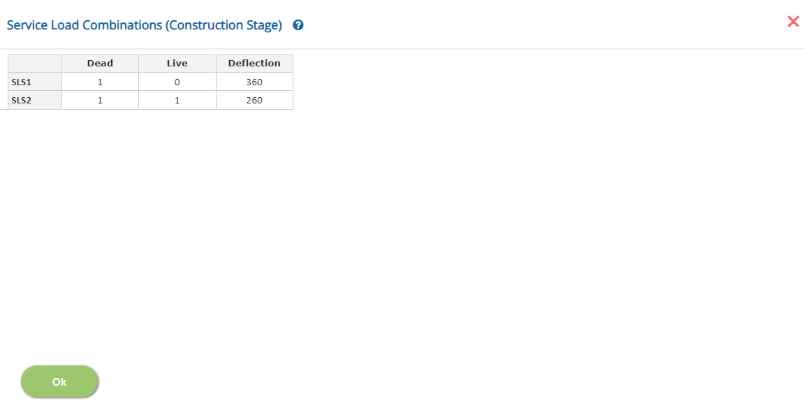
In this pop-up, n - number of Load Combinations (SLS / ULS) can be added with factors for the load cases selected in the Loads pop-up.
Load Cases FactorsLoad Case Description is displayed in each spreadsheet column. Enter the load factor for every load case and for each load combination.
↔ Range: -10 to 10 (SLS) -20 to 20 (ULS)
Enter the span / deflection allowable ratio against each combination (Service Combination only) For final stage combination, add asteric mark '*' to check the deflection using long term elastic concrete modulus.
↔ Range: 10 to 2000
- Note 1: For Dead Load case type, which is the first column, the factor should be a positive non-zero value.
- Note 2: Ultimate Load Combinations are only for LRFD Method for the design of the beam.
Design Setting
Setting for Design Data such as Concrete Properties and Steel Properties are presented in this section. This setting pop-up can be accessed by clicking the bottom panel below the left navigation.
Concrete Properties
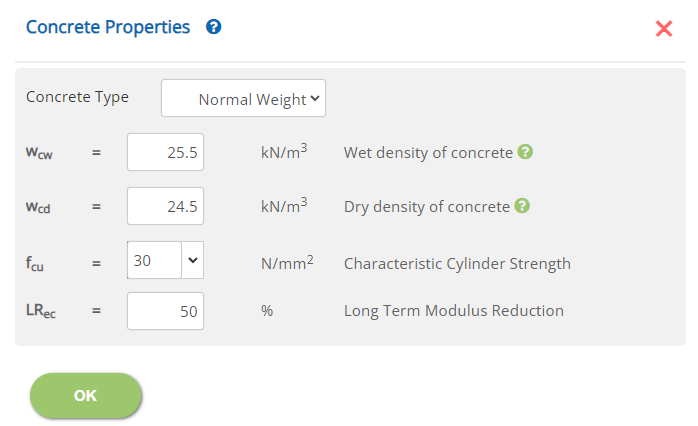
Concrete Type
Select the type 'Normal Weight' or 'Light Weight' from the drop down menu. This is to calculate the elastic properties of the concrete.
Wet Density of Concrete - Wcw
Enter the wet density of concrete - used for self weight calculation during construction stage. (Not applicable if shoring is used in the construction stage)
↔ Range: 5 to 35 kN/m3 (31.82 to 222.8 pcf)
Dry Density of Concrete - Wcd
Enter the dry density of concrete - used for self weight calculation at final stage.
↔ Range: 5 to 35 kN/m3 (31.82 to 222.8 pcf)
Characteristic Cylinder Strength - fcu
Enter the characteristic cylinder strength of the concrete (Concrete Grade)
↔ Range: 10 to 100 N/m22 (1.5 to 14.5 ksi)
Long Term Modulus Reduction LRec
Enter the percentage of reduction for the short term concrete modulus to calculate the long term deflection.
↔ Range: 0 to 90 %
Steel Properties
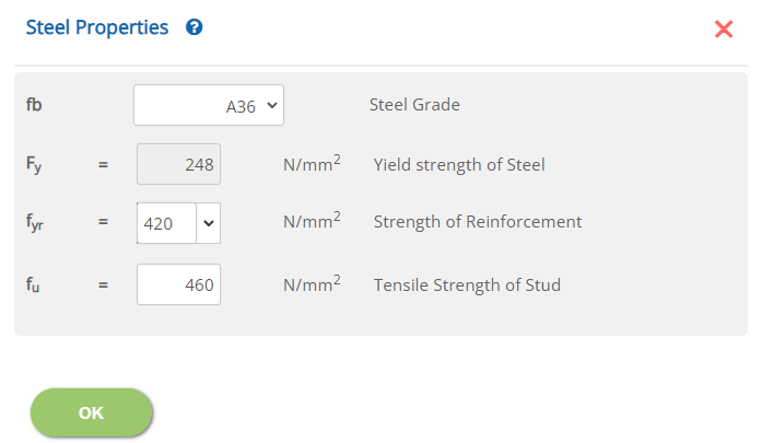
Steel Grade - fb
Select the steel grade for the steel beam from the drop down menu.
Yield strength of Steel - Fy: Not editable for standard grade
↔ Range: 50 to 2000 N/mm2 (7.3 to 290.1 ksi)
Strength of Reinforcement - fyr
↔ Range: 150 to 2000 N/mm2 (21.8 to 290.1 ksi)
Tensile Strength of Stud - fu
↔ Range: 50 to 4000 N/mm2 (7.3 to 580.2 ksi)
Error Handling
Errors and Warnings are generated to prevent any inadvertent error and ensure data integrity in the input data. This section describes how to handle the errors and warnings. These errors are displayed at the bottom of the input page when the data in one or more input fields invalidate each other. Calculation can not be run if there is any error in the input data. While the calculation can proceed with warnings, the user must take a note of it and make necessary correction.
- Note: Out of range errors are displayed next to the input field.
| # | Error | Reason | Solution |
|---|---|---|---|
| 1 | Warning: Insufficient space for studs | When the studs whether one or two in a group in the Deck and Slab page spills out of the steel section flange width or the metal deck rib width, this warning is generated. | Check the diameter of the stud selected at page Deck and Slab or the metal deck rib trough width at the pop up Deck Details. |
| 2 | Warning: The net concrete slab top thickness is than 25mm (1.0in) | When the deck slab total thickness is specified, the net top slab thickness (Total slab thickness - metal deck depth) should have sufficient thicness to ensure proper concreting. | Check the overall deck slab thickness at page Deck and Slab considering the metal deck rib depth at the pop up Deck Details. |
| 3 | Warning: The end span for the studs is less than Span / 10 | When different stud is selected for the end span, the selected length should preferably be more than Span/10. When this is below Span / 10, this warning is generated. | Check and change the end span stud extend at page Stud. (Zero length means no end span studs is applicable.) |
| 4 | Warning: The end span for the studs is extending very close to mid span | When different stud is selected for the end span and midspan, the selected length for the end span stud should preferably be less than 0.45 span. When this is more than 0.45 Span, this warning is generated. | This is to alert the user of unsual selection of end span studs extend. Check the end span studs extend and make necessary change as required at page Stud. |
| 5 | Warning: The stud head has the concrete cover less than 15mm (0.5in) | When the height of the stud is specified such that the cover of concrete above the head of the stud is less than 15mm. | This is to prevent specifying the height of the stud without much concrete cover. Check the overall concrete thickness at page Deck and Slab and or the stud height at page Stud. |
| 6 | Error: Depth of Slab should be greater than Depth of Deck | The overall depth of the slab is found to be less than the metal deck depth. Check the oveall thickness of the slab and or the metal deck rib depth. | Check the overall deck slab thickness at page Deck and Slab considering the metal deck rib depth at the pop up Deck Details. |
| 7 | Error: End Span for the studs shall be less than the Span / 2 | When different stud is selected for the end span, the selected length cannot upto or more than midspan. | Check the end span studs extend and make necessary change as required at page Stud. |
| 8 | Error: Height of Stud should be lesser than Depth of Slab | When the height of the stud is specified such that the head of the stud is above the concrete surface. | Check the overall concrete thickness at page Deck and Slab and or the stud height at page Stud. |
| 9 | Error: The stud should extend above the deck | When the height of the stud is specified such that the head of the stud is not extending into the top slab thickness. In order for the stud to be effective in transferring the concrete conmpression to the steel beam for composite action, this is a requirement. | Change the height of the stud and change at the page at page Stud or the total slab depth at Deck and Slab as required. |