Help Topics
ECHOLLOWSLAB - Precast Concrete Hollowcore Slab Design
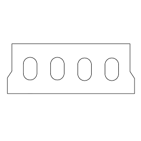
This part of user manual describes how to use ECHOLLOWCORE for the design of Precast Concrete Hollow Core Slab. ECPlus applications are designed as wizard type which is a step by step guided input procedure. If you are new to ECPlus applications, click here for a general guidance.
Prerequisites: The user is expected to have a basic understanding of precast and prestressed concrete design.
The minimum input data required to use this application is as follows:
- ❶ Hollow Core Slab Geometry
- ❶ Concrete Grade
- ❷ Prestressing Details
- ❸ Loading Details
Design Options
This page allows to select the design standard and unit.
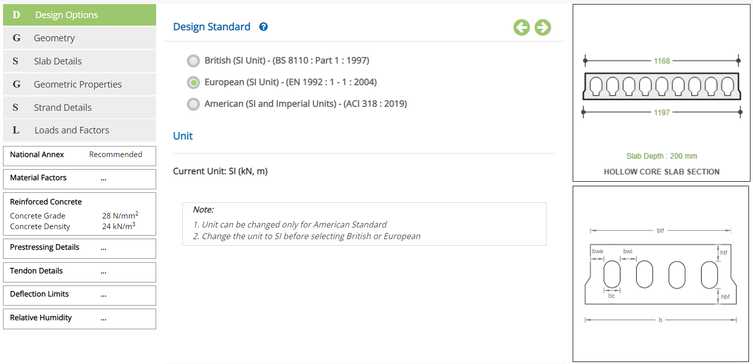
Design Standard
Select the National Standard for the design.
Available Standards: ☉British, ☉European and ☉American.
British and American Standards are not available in current version.
Unit
It displays the active unit. The unit Change button is displayed when ☉American Standard is selected.
British and European Standards can not be selected when Imperial unit is active.
Change
Click this button to open the unit change pop-up dialog.
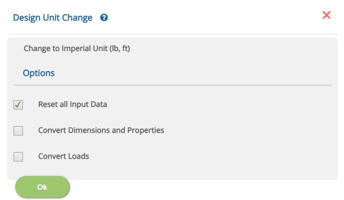
☐ Reset all Input Data
This option will reset the input data for the new unit. This option is recommended if the job is new and no input data has been entered yet.
☐ Convert Dimensions and Properties
This option allows to convert all the previously entered input data except Load data to the new unit.
☐ Convert Loads
This option allows to convert previously entered load data to the new unit.
Note: Both Convert Dimensions and Properties and Convert Loads options can be used simultaneously to convert all the previously entered input values to the new unit.
- Note: While the program attempts to reasonably convert the rebar sizes equivalent to the new unit, the user should verify the reinforcement pages of pad and pedestal to ensure that the conversion has been applied as expected.
Incorrect option leads to out of range errors and should be manually corrected.
Geometry
This page allows the input of geometry details of hollowcore slab.
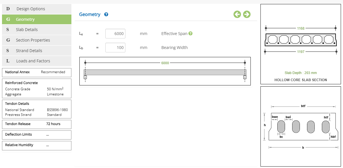 Effective Span - Le
Enter the effective span of the hollow core slab (It is not the clear span).
↔ Range: 500 to 10000 mm
Enter the bearing width of the support.
↔ Range: 50 to 5000 mm
Slab Details
This page allows the input of cross sectional details of hollow core slab.
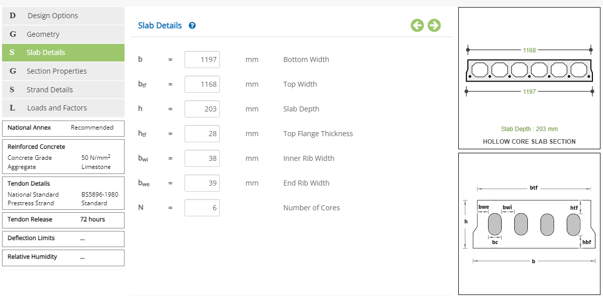 Bottom Width of Slab - b
Enter the bottom width of the slab.
↔ Range: 190 to 5000 mm
Enter the width of the top flange.
↔ Range: 180 to 5000 mm
Enter the overall depth (thickness) of the slab.
↔ Range: 50 to 1000 mm
Enter the top flange thickness of the slab.
↔ Range: 15 to 500 mm
Bottom Flange Thickness is required if section properties are to be calculated by program. It is available in Section Properties page for the 'Program' option.
Enter the inner / end rib width (between the hollow cores) of the slab.
↔ Range: 15 to 500 mm
Enter the number of (hollow) cores.
↔ Range: 2 to 15
The diameter / size of the core is auto calculated by program based on the dimensions entered above.
Section Properties
This page allows the selection of the options if the section properties are calcualted or entered by the user and the input of geometric properties of hollow core slab.
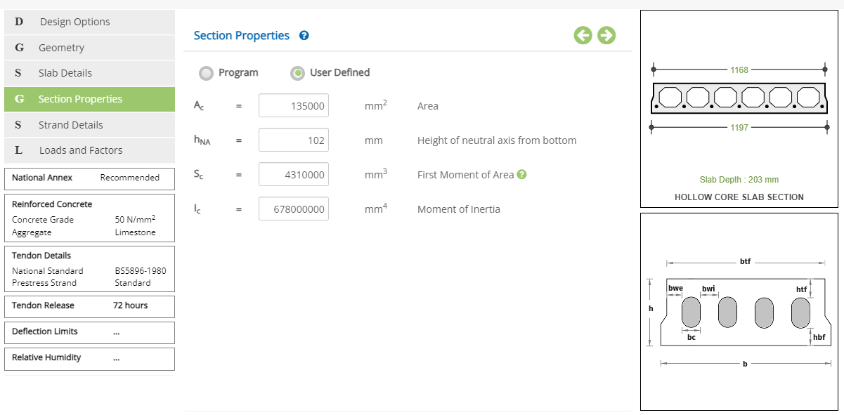
Select the section properties option.
☉Program, and ☉User Defined.
Enter the net concrete area of the hollow core slab cross section.
↔ Range: 10,000 to 2,000,000 mm2
Enter the height of the neutral axis from bottom of the slab.
↔ Range: 10 to 1000 mm
Enter the first moment of area for the area above the neutral axis.
↔ Range: 1,000,000 to 100,000,000 mm3
Enter the moment of inertia about the neutral axis.
↔ Range: 10,000,000 to 100,000,000,000 mm4
Enter the bottom flange thickness of the slab. This is to calculate the geometrical properties of the section for 'Program' option.
↔ Range: 15 to 500 mm
- Note: Section properties are crucial to the calculation of the section capacity. The user is strongly advised to cross verify the 'User Defined' section properties with that of 'Program' generated ones.
Strand Details
This page allows the input of strand details.
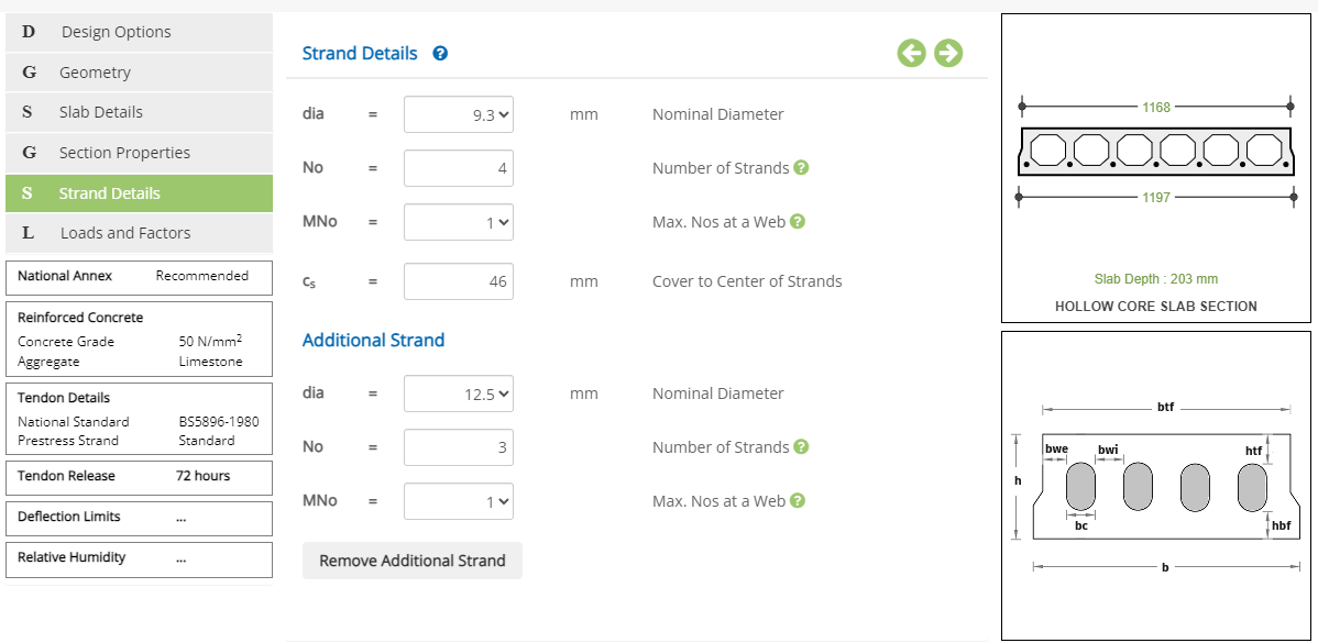 Nominal Diameter - dia
Select the nominal diameter of the strand from the drop down. This nominal diameter drop down values will vary based on Strand Type in Prestressing Details popup.
Number of Strands - NoEnter the number of strands.
↔ Range: 1 to 20
Enter the max number of strands placed in a web. (See the picture for example)
↔ Range: 1 to 20
Enter the cover to the CG of all strands from bottom.
↔ Range: 10 to 200 mm
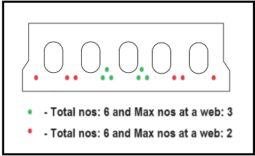
- Note: There is a provision to choose different dia of strand and the numbers. Click the buttons Add Strain and Remove Additional Strand to add or remove the additional strands.
Loads and Factors
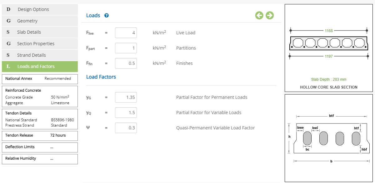
This page allows the input of the loads and factors.
Loads
Live Load - FliveEnter the live load acting over the hollowcore slab.
↔ Range: 0 to 300 kN/m2
Enter the load due to partition walls acting over the holloecore slab.
↔ Range: 0 to 300 kN/m2
Enter the loads due to floor finishes.
↔ Range: 0 to 300 kN/m2
Load Factors
Partial Factor for Permanent Loads - γGEnter the partial load factor for permanent loads.
↔ Range: 0.1 to 20
Enter the partial laod factor for variable loads.
↔ Range: 0.1 to 20
Enter the quasi - permanent variable load factor.
↔ Range: 0 to 10
Design Setting
Setting for various Design Data such as Concrete, Prestressing Details, Tendon Details, Deflection Limits and Relative Humidity are presented in this section. This setting pop-up can be accessed by clicking the bottom panel below the left navigation.
National Annex
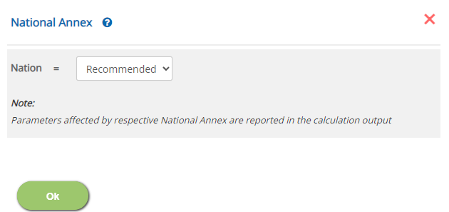
Select the National Annex after selecting the European Standard in Design Option.
 Nation
Select the National Annex option for the relevant factors to be considered in the design.
Reinforced Concrete Properties (BS EN 1992-1-1)
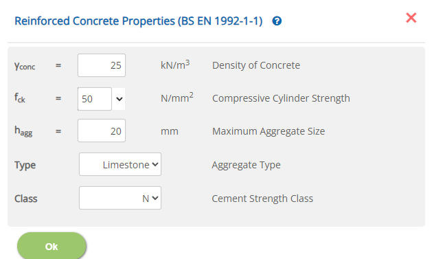
Enter the reinforcement concrete properties on selection of European Standard from Design Option.
 Density of Concrete - γconc
Enter the dry density of the concrete.
↔ Range: 10 to 40 kN/m3
Enter the characteristic compressive cylinder strength of the concrete.
↔ Range: 10 to 150 N/mm2
Enter the maximum size of aggregate.
↔ Range: 5 to 60
Aggregate Type - Type
Choose the type of aggregate from the drop down.
▽ Basalt: Select this option to choose Basalt as type of aggregate.
▽ Limestone: Select this option to choose Limestone as type of aggregate.
▽ Quartzite: Select this option to choose Quartzite as type of aggregate.
▽ Sandstone: Select this option to choose Sandstone as type of aggregate.
Cement Strength Class - Class
Select the class of cement strength.
▽ N: Select this option to choose N as cement strength class.
▽ R: Select this option to choose R as cement strength class.
▽ S: Select this option to choose S as cement strength class.
Tendon Details
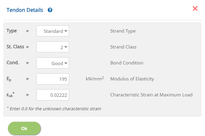
Enter the tendon details such as its type, class and bond condition.
 Strand Type
Select the type (grade) of the tendon (Strand or Wire)
▽ British, European and American
Select the grade from the respective standard from the dropdown list.
Select the strand class
▽ 1, 2 and 3 Select the class from the list.
Select the Bond Condition
▽ Good, Fair/Poor Select the bond condition of the strand with concrete.
Select the modulus of elasticity of the prestressing strand.
↔ Range: 100 to 300 kN/mm2
Select the characteristic strain at maximum load. (Enter zero for default value)
↔ Range: 0 to 0.05
This value is defined in certain National Annexes. If the national annex defines this value, the user input is ignored.
Tendon Release
Enter the details such as tendon release, installation and loading time.
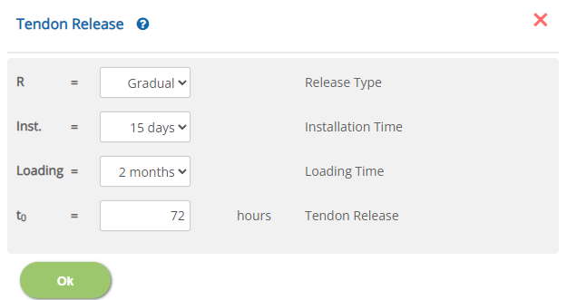 Release Type - R
Select the type of tendon release.
▽ Gradual: Select this option to use gradual tendon release.
▽ Sudden: Select this option to use sudden tendon release.
Select the time for slab installation.
▽ 15 days: Select this option to use 15 days as tendon installation time.
▽ 1 month: Select this option to use 1 month as tendon installation time.
▽ 2 months: Select this option to use 2 months as tendon installation time.
▽ 3 months: Select this option to use 3 months as tendon installation time.
▽ 6 months: Select this option to use 6 months as tendon installation time.
▽ 1 year: Select this option to use 1 year as tendon installation time.
▽ 3 years: Select this option to use 3 years as tendon installation time.
Select the time for loading (into service time).
▽ 2 months: Select this option to use 2 months as loading time.
▽ 3 months: Select this option to use 3 months as loading time.
▽ 6 months: Select this option to use 6 months as loading time.
▽ 1 year: Select this option to use 1 year as loading time.
▽ 3 years: Select this option to use 3 years as loading time.
▽ 10 years: Select this option to use 10 years as loading time.
▽ Infinity: Select this option to use infinity loading time.
Enter the tendon release time in hours.
↔ Range: 5 to 1000 hours
Deflection Limits
This popup allows to enter the deflection limits for Initial camber, deflection after installation and Long term deflection.
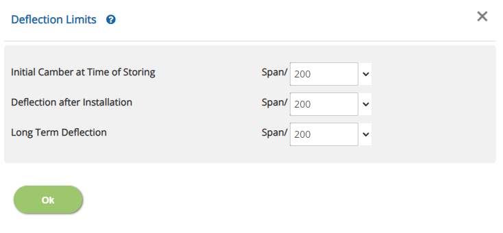 Initial Camber at Time of Storing
Select / Enter the initial camber ratio (Span/camber) at the time of storing.
↔ Range: 5 to 2500
Select / Enter the limit of deflection ratio (Span/deflection) after installation.
↔ Range: 5 to 2500
Select / Enter the long term deflection ratio (Span/deflection) due to quasi permanent loads.
↔ Range: 5 to 2500
Relative Humidity
This popup allows to enter the relative humidity details.
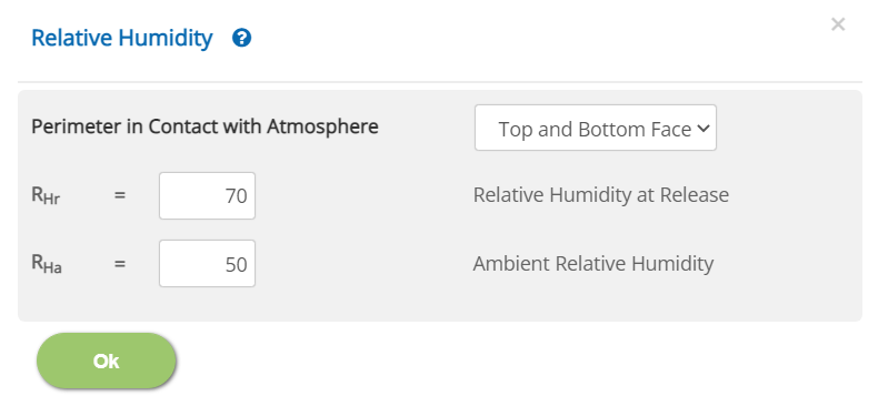 Perimeter in Contact with Atmosphere
Select the face(s) that is(are) in contact with the atmosphere from the drop down.
▽ Bottom Face Only: Select this option if bottom face alone is in contact with the atmosphere.
▽ Top and Bottom Face: Select this option if both top and bottom faces are in contact with the atmosphere.
Enter the relative humidity at realese.
↔ Range: 10 to 100 %
Enter the ambient relative humidity.
↔ Range: 10 to 100 %
Error Handling
Errors and Warnings are generated to prevent any inadvertent error and ensure data integrity in the input. This section describes how to handle the errors and warnings. These errors are displayed at the bottom of the input page when the data in one or more input fields invalidate each other. Calculation can not be run if there is any error in the input data. While the calculation can proceed with warnings, the user must take a note of it and make necessary correction.
- Note: Out of range errors are displayed next to the input field.
| # | Error | Reason | Solution |
|---|---|---|---|
| 1 | Error: Max no of strands at a web cannot exceed the total no of strands | When the maximum no of strands at a web is specified in Strand Details is more than the total number of those strands, this error is generated. | Check the maximum nos of strands at web and total number of strands in Strand Details and ensure consistency of strands arrangement. |
| 2 | Error: Ambient relative humidity should be less than or equal to (Rhr – 5) | Relative Humidity at Release has been specified 5 % lesser of Ambient Relative Humidity at Relative Humidity. | Check the values at Relative Humidity to ensure the required consistency. |
| 3 | Error: Bearing Width should be lesser than or equal to effective span of slab | The bearing width at the geometry page Geometry is erraneously specified abnormal. | Check the bearing width or effective span at the geometry page Geometry and correct the input values accordingly. |
| 4 | Error: Loading time should be greater than the installation time | The loading time has been specified in Tendon Release before the installation time. | Check the loading and installation time at the Tendon Release pop-up and make necessary correction. |
| 5 | Error: Installation time should be greater than the tendor release time | The tendon release time has been specified in Tendon Release after the installation time. | Check the tendon release and installation time at the Tendon Release pop-up and make necessary correction. |
| 6 | Error: Cross - sectional area should be less than or equal to (b * h) | The cross sectional concrete area has been specified in Section Properties page for 'User Defined' option more than the area possible within the dimensions specified at Slab Details. | Check the section properties at Section Properties and or slab dimensions at Slab Details and make necessary correction. |
| 7 | Error: Neutral Axis should be less than the slab depth (Thickness) | The neutral axis from the bottom of the slab at Section Properties page for 'User Defined' option is not less tha the slab depth specified at Slab Details. | Check the section properties at Section Properties and or slab dimensions at Slab Details and make necessary correction. |
| 8 | Error: Cover to strand should be less than or equal to half of the slab depth | The cover of the strand has been speicifed at Strand Details more than half of the slab depth at Slab Details. | Cehck the cover of the at Strand Details> and or the slab depth at Slab Details and make necessary corrections. |
| 9 | Error: Thickness of top flange should be less than or equal to Slab Depth / 2 | The thickness of the top flange has been speicifed at Slab Details more than half of the slab depth. | Cehck the thickness of the top flange and or the slab depth at Slab Details and make necessary corrections. |
| 10 | Error: Thickness of bottom flange should be less than or equal to Slab Depth / 2 | The thickness of the bottom flange has been speicifed at Section Properties as more than the half of the slab depth at Slab Details. | Cehck the thickness of the bottom flange at Section Properties for 'Program' option and or the slab depth at Slab Details and make necessary corrections. |
| 11 | Error: Width of Top Flange should be less than or equal to bottom width of slab | The width of the top flange has been Slab Details as more than the bottom width of the slab. | Cehck the width of the top flange and bottom flange at Slab Details and make necessary corrections. |
