Help Topics
ECBASEPLATE - Column Base Plate Fixed Design
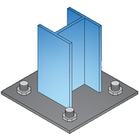
This part of user manual describes how to use ECBASEPLATE for the design of Column base plate fixed. ECPlus applications are designed as wizard type which is a step by step guided input procedure. If you are new to ECPlus applications, click here for general guidance.
Prerequisites: The user is expected to have a basic understanding of column baseplate design concepts.
The minimum input data required to use this application is as follows:
- ❶ Structural Steel Section
- ❷ Baseplate Size
- ❸ Bolts and Anchorage
- ❹ Design Loads and Moment
Design Options
This page allows to select the design standard and the unit.
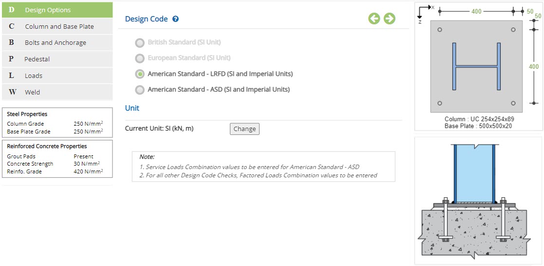 Design Code
Select the relevant Code Standard for design.
Available Standard Codes: ☉ British, ☉ European and ☉ American.
American design Standard has option to select the design method:
☉ LRFD or ☉ ASD
British and European Standards are not available in the current version.
UnitIt displays the active unit. The unit Change button is displayed when ☉American Standard is selected.
Design Unit Change
Click this button to open the unit change pop-up dialog.
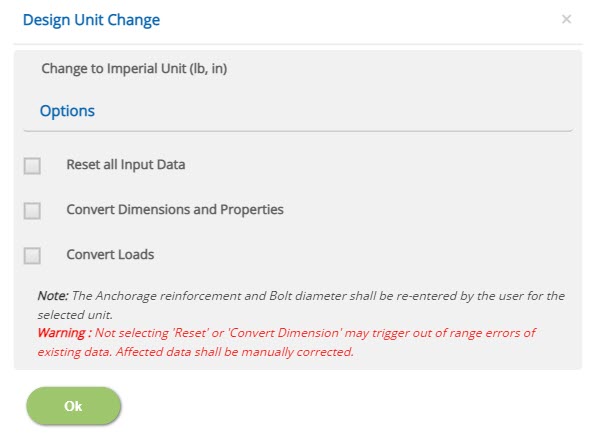
☐ Reset all Input Data
This option will reset the input data for the new unit. This option is recommended if the job is new and no input data has been entered yet.
☐ Convert Dimensions and Properties
This option allows to convert all the previously entered input data except Load data to the new unit.
☐ Convert Loads
This option allows to convert previously entered load data to the new unit.
Note: Both Convert Dimensions and Properties and Convert Loads options can be used simultaneously to convert all the previously entered input values to the new unit.
Column and Base Plate
This page allows to select column section and enter the base plate details.
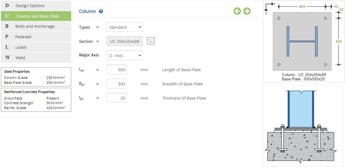 Type
TypeSelect the option between Standard, I Sec - User, RHS Sec - User or SHS Sec - User.
▽ Standard: Select this option to design base plate per British, Euro or American Standard.
▽ I Sec - User: Select this option for Base plate to assign as user defined I Section.
▽ RHS Sec - User: Select this option for Base plate to assign as user defined RHS Section.
▽ SHS Sec - User: Select this option for Base plate to assign as user defined SHS Section.
Steel Section Table
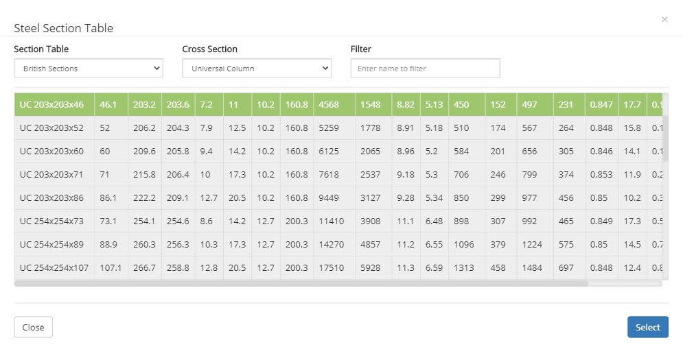
By choosing the Type as Standard , the Cross-sectional properties will be displayed for the selected Section. To change the selected Section, click button, a pop-up dialog box displays a list of standard section based on option listed in menu Section Table & Cross Section
 ▽ Section Table:
Select this option to have list of Standard British, European or AISC Sections.
▽ Cross Section:This option allows user to select wider or narrow flange beam like UB, UC, IPE, HE, W, M, etc., based on selection at Section Table menu.
▽ Filter:Based on name by user and with option selected at Section Table and Cross Section , a filtered member list will be displayed.
I Sec User
By choosing the Type as I Sec User , enter Cross-sectional properties.
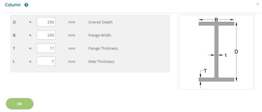 Overall Depth - D
Enter overall depth of the section.
↔ Range: 50 to 1500 mm (1.5 to 60 inches)
Enter the flange width of the section.
↔ Range: 50 to 1500 mm (1.5 to 60 inches)
Enter the thickness of flange of the section.
↔ Range: 3 to 100 mm (0.1 to 4 inches)
Enter the thickness of web of the section.
↔ Range: 2 to 100 mm (0.05 to 4 inches)
RHS Sec User
By choosing the Type as RHS Sec User , enter Cross-sectional properties.
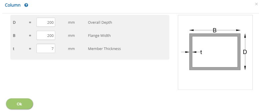 Overall Depth - D
Enter overall depth of the section.
↔ Range: 50 to 1500 mm (1.5 to 60 inches)
Enter the flange width of the section.
↔ Range: 50 to 1500 mm (1.5 to 60 inches)
Enter the member thickness of the section.
↔ Range: 2 to 100 mm (0.05 to 4 inches)
SHS Sec User
By choosing the Type as RHS Sec User , enter the Cross-sectional properties.
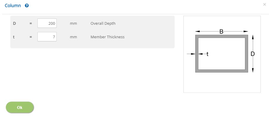 Overall Depth - D
Enter overall depth of the section.
↔ Range: 50 to 1500 mm (1.5 to 60 inches)
Enter the member thickness of the section.
↔ Range: 2 to 100 mm (0.05 to 4 inches)
Major Axis
Select the option between Z-Axis and X-Axis,
This is the column orientation in the structural analysis model from which the loads are imported to the design. Orientation will affect the direction of the loads/reactions that will be considered for the baseplate design.
Base Plate
 Length / Breadth of Base Plate - Lpl / Bpl
Enter the length / breadth of the base plate. Length is the dimension along the depth of the column section.
↔ Range: 200 to 2000 mm (8 to 80 inches)
Enter the thickness of the base plate.
↔ Range: 3 to 50 mm (0.1 to 6 inches)
Bolts and Anchorage
This page allows to enter bolt and anchorage details.
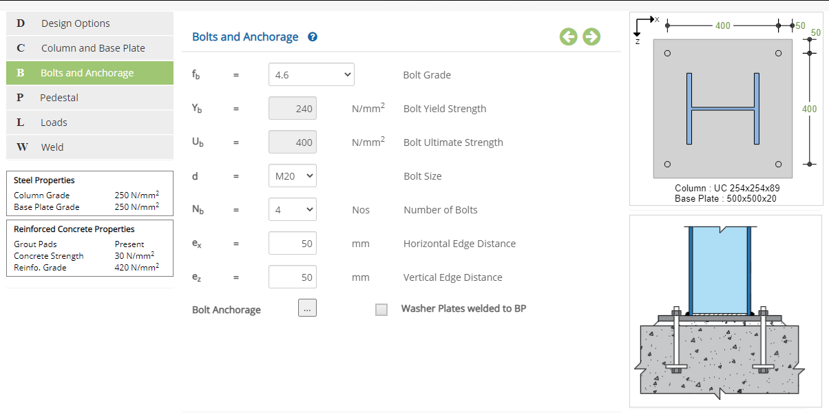
Holding Down Bolts
Bolt Grade - fbSelect the grade of bolt from the drop down list.
Bolt Yield / Ultimate Strength - Yb / UbDisplays yield / ultimate strength of bolt based on bolt grade. Enter bolt yield / ultimate strength in case of user defined bolt grade.
↔ Range: 100 to 1000 N/mm2 (15 to 145 ksi)
Select the size of bolt from the drop down list.
Number of Bolts - NbSelect the total number of bolts from the drop down list. Available number of bolts are ▽ 4, ▽ 6 and ▽ 8
Horizontal / Vertical Edge Distance - ex / ezEnter horizontal / vertical edge distance of holding down bolt.
↔ Range: >= 0 mm (>= 0 inches)
☐ Washer Plates welded to BP: Check this option if washer plates are welded to the base plate. When this option is selected, all bolts are considered to resist the shear force. If not checked, only the bolts on one side are considered effective to resist applied shear.
Bolt Anchorage
Click this button to open the bolt anchorage pop-up dialog.
AnchorageSelect whether anchorage is ▽ Defined or ▽ Not Defined from the drop down.
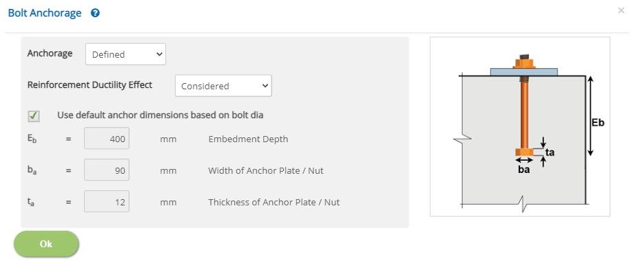
Anchorage = Defined
Reinforcement Ductility EffectCheck if reinforcement ductility is ▽Considered or ▽Not Considered from the drop down. If reinforcement ductility is selected, the reinforcement shall be defined in the pedestal page.
☐ Use default anchor dimensions based on bolt dia: Check this option to use predefined anchor plate dimensions based on size of anchor.
Embedment Depth - EbEnter the embedment depth of anchor plate.
↔ Range: 150 to 3000 mm (5 to 120 inches)
Enter the width of the anchor plate / nut.
↔ Range: 0 to 300 mm (0 to 10 inches)
Enter the thickness of the anchor plate / nut.
↔ Range: 0 to 100 mm (0 to 15 inches)
Anchorage = Not Defined
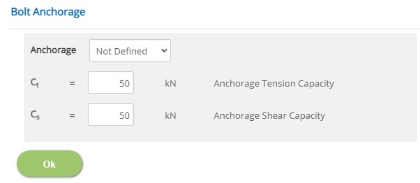 Anchorage Tension / Shear Capacity - Ct / Cs
Enter the anchorage tension / shear capacity of the bolt.
↔ Range: 0 to 5000 kN (0 to 1125 kips)
Pedestal
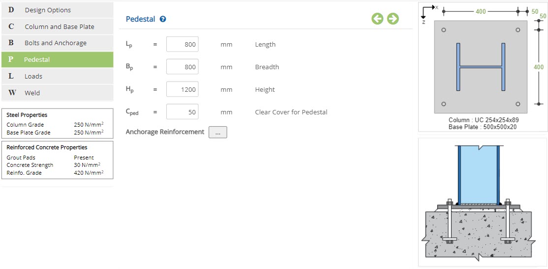 Length / Breadth - Lp / Bp
Enter the length / breadth of the pedestal.
↔ Range: 250 to 1500 mm (10 to 50 inches)
Enter the height of the pedestal.
↔ Range: 150 to 2000 mm (5 to 75 inches)
Enter the clear cover for pedestal.
↔ Range: 15 to 150 mm (0.5 to 6 inches)
Anchorage Reinforcement
Click this button to open the anchorage reinforcement pop-up dialog.
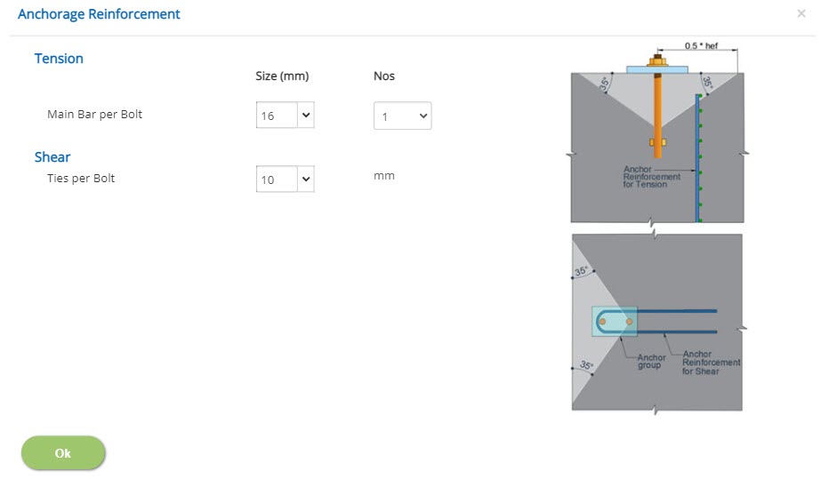
Tension
Size (mm)Enter the size of main reinforcement.
↔ Range: 4 to 60 mm
Select the number of main reinforcement from the drop down menu.
↔ Range: 1 to 4 Nos
Shear
Size (mm)Enter the size of ties per bolt.
↔ Range: 4 to 60 mm
Loads
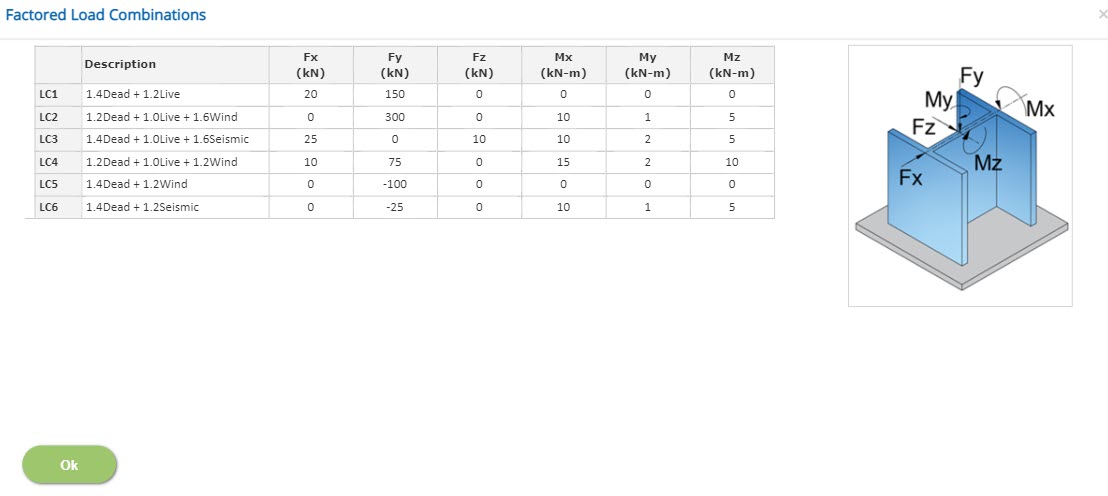
Click this button to open the factored load combinations popup to enter input for different load combinations. Loads are entered as force in X, Y, Z directions and moment about X (longitudinal axis) and Z (transverse axis) directions.
Fx / Fy / Fz
↔ Range: -100000 to 100000 kN (-100000 to 100000 kips)
Mx / My / Mz
↔ Range: -100000 to 100000 kN-m (-100000 to 100000 kips.in)
Weld
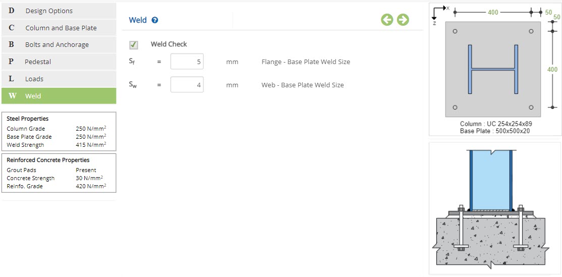
☐ Weld Check: Check this option to include weld check.
Flange / Web - Base Plate Weld Size - Sf / SwEnter the base plate weld size for flange / web.
↔ Range: >= 0 mm (>= 0 inches)
Design Setting
Setting for various Design Data such as Steel grade, Reinforced concrete properties and Weld strength properties. This setting pop-up can be accessed by clicking the bottom panel below the left navigation.
Steel Properties
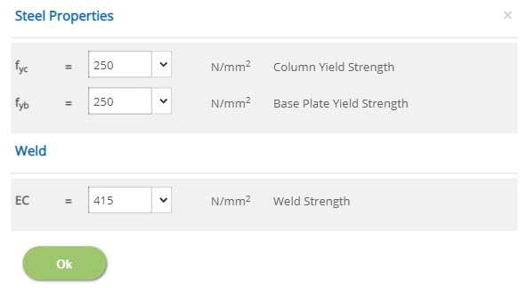
Steel Properties
Column / Base Plate Yield Strength - fyc / fyb↔ Range: 200 to 500 N/mm2 (25 to 75 ksi)
Weld
Weld Strength - EC↔ Range: 300 to 800 N/mm2 (20 to 150 ksi)
Reinforced Concrete Properties
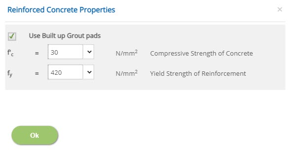
☐ Use Built up Grout pads: Check this option to use built up grout pads. When this is checked, the shear strength of the anchor bolt is reduced according to clause 17.7.1.2.1. This is to include the effect of anchor bolt bending that might arise due to cracking of grout.
Compressive Strength of Concrete - f'c↔ Range: 15 to 100 N/mm2 (1 to 15 ksi)
Yield Strength of Reinforcement - fy↔ Range: 150 to 2000 N/mm2 (20 to 300 ksi)
Error Handling
Errors and Warnings are generated to prevent any inadvertent error in the input data. This section describes how to handle the errors and warnings. These errors are displayed at the bottom of the input page when the data in one or more input fields invalidate each other.
- Note: Out of range errors are displayed next to the input field.
| # | Error | Reason | Solution |
|---|---|---|---|
| 1 | Warning : Bolts placed closer than 5.0d along length | Bolts are placed closer than 5 times diameter of bolt along length direction. | Bolt should be provided such that spacing is greater than 5 times the diameter of bolt along length direction. |
| 2 | Warning : Bolts placed closer than 5.0d along breadth | Bolts are placed closer than 5 times diameter of bolt along breadth direction. | Bolt should be provided such that spacing is greater than 5 times the diameter of bolt along breadth direction. |
| 3 | Warning : Anchor plate size is less than 3.0d | Size of anchor plate provided is lesser than 3 times of diameter. | Size of anchor plate should be provided such that, it is greater than 3 times of diameter. |
| 4 | Warning : Bolts placed closer than 1.25d to flange | Bolts are placed closer than 1.25 times diameter to flange. | Bolt should be provided such that spacing is greater than 1.25 times the diameter to flange. |
| 5 | Warning : Outer bolts subtent angle > 45° to flange. Plate bending analysis may be incorrect | Bolts provided lies at an angle greater than 45° of line drawn from outer edge of flange of the column. | Bolt should be provided such that it lies with 45° of line drawn from outer edge of flange of column. |
| 6 | Warning : Edge Distance less than 1.5d length direction | Edge distance provided is less than 1.5 times diameter along length direction. | Edge distance should be provided such that it is greater than 1.5 times diameter along length direction. |
| 7 | Warning : Edge Distance less than 1.5d breadth direction | Edge distance provided is less than 1.5 times diameter along breadth direction. | Edge distance should be provided such that it is greater than 1.5 times diameter along breadth direction. |
| 8 | Warning : Bolts to Pedestal Edge less than 6.0d in length direction | Distance between bolts and pedestal edge is lesser than 6 times diameter in length direction. | Distance between bolts and pedestal edge should be provided such that it is greater than 6 times diameter in length direction. |
| 9 | Warning : Bolts to Pedestal Edge less than 6.0d in breadth direction | Distance between bolts and pedestal edge is lesser than 6 times diameter in breadth direction. | Distance between bolts and pedestal edge should be provided such that it is greater than 6 times diameter in breadth direction. |
| 10 | Error : Bolts clash in the direction along length | Bolts provided are clashing with each other along length direction. | Care should be taken to avoid clashing between bolts along length direction. |
| 11 | Error : Bolts clash in the direction along breadth | Bolts provided are clashing with each other along breadth direction. | Care should be taken to avoid clashing between bolts along breadth direction. |
| 12 | Error : Anchor plate size is less than 1.0d | Size of anchor plate is lesser than the diameter. | Size of anchor plate should be provided, such that it is greater than the diameter provided. |
| 13 | Error : Anchor plate size is too big to the bolt spacing | Size of anchor plate provided is larger to the bolt spacing. | Size of anchor plate provided should accommodate with the bolt spacing provided. |
| 14 | Error : Bolts along length should be outside the flange | Bolts provided are located inside the flange. | Care should be taken to locate bolts outside the flange. |
| 15 | Error : Outer bolts subtent angle > 50° to flange. Plate bending analysis will be incorrect | Bolts provided lies at an angle greater than 50° of line drawn from outer edge of flange of the column. | Bolt should be provided such that it lies with 50° of line drawn from outer edge of flange of column. |
| 16 | Error : Bolts out of baseplate in length direction | Bolts provided are located outside the baseplate in length direction. | Bolt should be provided such that they are located within the base plate in length direction. |
| 17 | Error : Bolts out of baseplate in breadth direction | Bolts provided are located outside the baseplate in breadth direction. | Bolt should be provided such that they are located within the base plate in breadth direction. |
| 18 | Error : Baseplate dimensions exceed Pedestal Dimensions | Base plate dimensions provided exceeds the pedestal dimensions. | Care should be taken such that base plate dimension provided is lesser than the pedestal dimensions. |
| 19 | Error : Bolt depth exceeding pedestal height | Depth of the bolt exceeds height of the pedestal. | Care should be taken such that the depth of bolt does not exceeds height of the pedestal. |
